Virtual World Domination is an interactive board game in which players can use
portable controllers to attack and defend territories and ultimately control all territories.
Input:
Virtual World Domination take in input from the controller's infrared lights which are sensed by the Play Station Eye, which has been modified by removing an infrared light sensor and adding a visible light filter in order to sense infrared light. It has also been modified to take in mouse clicks for versatility.
game board
Output:
The game board is projected onto a flat surface using a basic projector. As a Territory's units increase of decrease, the numbers to the right of the Territory names increase and decrease correspondingly. In order to keep track of the Territory's owner, each player is assigned a color. This color is displayed behind their name during their turn and behind the Territories they own, which changes dynamically as Territories are conquered. An info box rests at the bottom of the board and gives players options as to how many they can defend with and how many they can attack with. Once the attacker and defender have chosen how many units to play with, dice are rolled and the results are projected on a panel in the center of the board.
Construction:
The physical parts of Virtual World Domination include a Play Station Eye (with the infrared filter removed and visible light filter added) and a projector to display the board which are both mounted on the ceiling, directed down to the flat surface. A computer is needed to run the program. Multiple finger lights were constructed from basic children's toys. We removed the LED and added an infrared light in it's place.
Software:
We used Processing 1.5.1 programming environment for all of Virtual World Domination's software. A finite state machine was used to step through the entire game with states including attackFrom (player selects which Territory to attack from), attackToNumber (the number of defending units from the attacker's chosen Territory), endTurn (moves to the next player's turn), and initialDraft (each player places initial units in Territories) to name a few. Multiple modules were also used. We included Dice, Players, Territory, World, SoftwareButtons, VideoDetection, MarkerDetection and TimeOptions.
Each Territory's information was from data files with their names, continents, location on the board, the number of territories in the continents, the number of bonuses, and the surrounding Territories.
In order to assure precision when selecting, we created two debugging modes. One mode stretches the camera width and height to match with the map's dimensions. The other calibrates the Territories info box to create the detection area.
The game board was customized for functionality with popup boxes and option buttons to prompt players throughout the game on who won, who lost, options for defending and attacking, canceling a move and ending a turn.
For players satisfaction, we added a clicking sound to play when the button is pressed. To assure that only one units is placed at a time, each time the infrared light is on it only allows for one "click". The Territories are also color coded to the players personal color for easy identification.
Part of the state machine
A map of the states
The mac mini we used to run the program
Modified Finger Lights
The modified finger lights in action
Problems:
As with any project, the Virtual World Domination had it's share of complications. The controller went through many modifications before reaching the final product. We started with a device similar to a flashlight, but it directed the light outward more than upward, giving an imprecise calibration. We used a remote that directed light directly up but realized that users would be standing at different locations around the board and would therefore assume the light would be in a different place depending on their angle. We finally created the finger lights you see above which can be placed directly over the desired location and be readable to the infrared camera simultaneously.
As we learned at the beginning of the course, the product must be user friendly most of all. We went through many trials in order to attain the ease of the user as well as keeping the enjoyment at a high level.
The purpose of this lab was to (1) send data to the computer using a sensor and have the computer graph the output visually, (2) send data from multiple sensors, and (3) create a wireless communication.
1 Way Serial Communication:
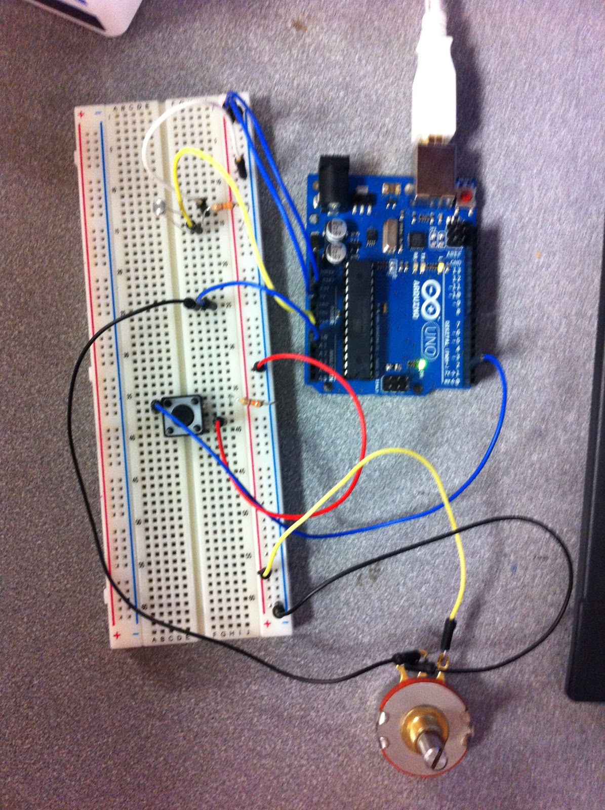
I began by connecting a potentiometer to an analog pin in the Arduino. I then programmed the Arduino to read the potentiometer and display the results on the Serial monitor using Serial.write():
Using Serial.write() made it challenging to understand the output because it was not sending the data as an ASCII character. To make it readable, I used an application called CoolTerm that shows the incoming bytes as ASCII or hexadecimal characters. The data then looked like this instead:
Next, I wanted to graph the values I was receiving from the potentiomenter with Processing. I set up my code with the correct library, window size, port and colors then created a method that read the input and printed it. Finally, I drew the graph with the input... and Viola!
I thought the potentiometer seemed rather boring so I switched sensors to this photoresistor for another neat effect!
2 Way Serial Communication:
Building on the one way serial communication, this time we added a photo resistor and a potentiometer for our analog sensors along with the digital button sensor. Next, we read in the values from each sensor and sent the data to an output of values on the monitor in an orderly way so that we could determine which values came from which sensors.
The photo resistor (top left) and potentiometer (bottom right) connected to analog while the button sensor (middle left) is connected to digital.
With our sensor data coming in cleanly, we then wanted to use them for a greater purpose: moving a ball across the screen. To do this, we added some color and position variables and created the desired shape. Then the sensor values were connected to the variables, moving the ball backward, forward, up and down when the sensors were used. When the button is pressed, the ball appears. When the analog sensor's values change, it changes the ball's direction.
coding the arduino
processing to draw our output
Wireless Communication:
For wireless communication, we paired up with another group so that we could be the "input" group, or the door bell, and the other group was the "output" group, or the chime.
To begin, we made sure to use 3.3V of power because that is what the XBee takes. The XBee is a piece of hardware that allows us to create communication wirelessly. We connected the XBee to the breadboard along with a button switch. While the other group mounted their XBee with a output sensor that gives off a clicking noise.
The next step was to configure the XBees by using a USB Serial adapter board. We labeled the input group "0" and output group "1" and followed the steps to connect the radios wirelessly to one another with a personal id of "2345".
Once they were configured as a pair, we programmed the devices. The input code determined if the button was pressed and if so, to create output on the serial port. The output code looked for the output on the serial port and created a clicking noise if the output was found.
Finally, we added an LED to the input side in order to send two way communication back from the chime group to the button group. We then added code to the chime group that gave feedback to the button group saying they received the signal. The button code was then modified to read the feedback and flash the LED confirming the communication.
The "doorbell" circuit with an LED and button
the "chime" circuit
Problems:
When trying the wireless communication for the first time, we were running into an error that told us our device was not in sync. This was because we did not disconnect the wire from the digital pin 0 before uploading. This caused unwanted data to take the place of the output we wanted.
For our Final Project, we have decided to create a
physically interactive Risk game. Risk is a tactical multiplayer board game that
separates the world into territories and players strive to gain power over the
whole world by attacking other player’s territories.
To make it physically interactive, we will implement processing with hardware and create a projection onto a table or board that will be the "game board". This board will be "touch sensitive" and will detect players moves throughout the game including attacks, dice rolls and loosing territories. For people new to this game, there will also be a "help" button to aid users in understanding and to help the game to be played fairly.
Board games are an important part of learning and require players to be engaged to their position. The benefits of board games are impressive and Risk in particular: enhancing educational skills by teaching where things are located on a map, building self confidence when the hard work and strategy paid off, developing social and mental skills by communicating with other players and knowing their next move and encouraging problem solving and logic. The purpose of this project will be to engage more people into wanting to play this game by making it interactive allowing players to have more fun and feel in control.
Here are some examples of projectors with human interactivity:
This is how the actual board game looks. Our display will look similar to this:
For
this assignment, we created a screen drawing using a background image of a tree
as well as a simple leaf shape in a simple yellow color. We first had an
ellipse draw for the leaf but decided to make it more detailed with the leaf
shape which is a png image. We
used variables to parameterize the characteristics of our design such as the
background color, size, image, mouse position and direction. This way, the
choices can be changed at the top of the file instead of searching through the code
to find replacements. We
developed an algorithm for changing the direction the leaf is “floating”. If
the down arrow is pressed, the y position increases and the x position
increases making the leaf go towards the bottom right corner. If the other
arrows are pressed, the leaf increases and decreases the x and y positions in
the correct direction to change the leaf’s location across the page. When the
mouse is clicked, the leaf is given the x and y position of the mouse.
Problems:
While creating our animation, we had difficulty getting the leaf to our desired shape. One way to create a more leaf like image would be to use vertex() and connect multiple points together with noStroke().
Coca-Cola
Freestyle is an interactive touch screen soda fountain that has been added to
numerous restaurants since its debut in 2009. It offers the customer more drink
options (over 125) than the previous 6-8 option beverage dispenser and takes up
less room with its built in ice dispenser.
It is
used when people order a drink at fast-food restaurants. A customer gets their
drink from a cashier and walks to the device. They first push their cup against
the lever to dispense the ice. Then they sit the cup down and use the touch
screen to choose the “base” drink and additional flavors. When they are satisfied with the drink and flavor, they push the
"pour" button until the cup is full.
When observing
people using it, I noticed that some skip the ice part entirely. I also
noticed that during peak hours, a long line forms because the machine
can only serve one person at a time. Some people choose to just have the basic
drink choices such as water, coke, and sprite. Others want all the customization
of cherry-vanilla flavored Pibb Xtra or orange-vanilla Hi-C. Many times people had trouble with the soda overflowing the cup. I also saw
that people wanted to try new combinations and took a lot of time choosing
an option, tasting it, pouring it out, and starting over, bothering others
waiting behind.
The
whole transaction takes about 30 seconds if the user knows what they want and
about a minute if they are trying to decide. Getting the ice takes the least
amount of time. To speed up the process, there could be a sign above the
machine with all of the “base” drinks and then the additional flavors to choose
from. This way people waiting in line can decide what they want before it is
their turn, making the process faster.
For
Norman and Crawford, to interact well, both sides must listen, think, and speak
well with each other. Lacking in one of
these areas will result in low interaction. The Coca-cola Freestyle has a high
degree of interaction. The user tells the machine what it wants (touches the
drink they want), the machine “listens” to what the user told it, “thinks”
about the selection, and “speaks” by dispensing the drink. The user listens to
the machine, thinks about what the machine will do, and “speaks” by putting
their cup in the right place so the machine can give the soda.
The purpose of this lab was to use a transistor to control a high-current DC motor from the Arduino using a transistor and to control the direction using an H-bridge and a Relay.
Transistor:
When circuits include high-current loads like a DC motor that require more than the Arduino can supply, we need a transistor to control it. A transistor has 3 prongs: the "base" connects to the Arduino's output, the "collector" is attached to the element that has the high current, and the "emitter" connects to ground.
I started by connecting a potentiometer and transistor to the circuit. I then connected the motor to a power supply separate from the Arduino. I then connected a diode to protect my transistor from "back voltage" that occurs when the motor is turned off or changes direction. Finally, code was added to turn the motor on and off every second and then was changed to control speed with the potentiometer!
Direction:
To take the circuit a step further, we wanted to change its direction. To do this, we used an H-bridge which allows us to switch the polarity, changing the motor's direction. I added a switch to the circuit as well as a motor and H-bridge. The H-bridge can be confusing at first because of its many parts and because it looks so similar to the shift registers! I have included a diagram which made connecting it easier. Once the motor was connected to the h-bridge and to an external power source, I added code that turned the motor one way with current was high and the other direction when low.
Relays are devices that can also control large loads. I implemented a relay to also change the direction of the motor, but with a more satisfying "click" when the change is made! To begin, I made a circuit that alternated between turning on 2 LEDs. I then reassembled the wires by reversing the flow of current and attached the motor:
Problems:
When working with the relays, there was a problem with the prongs not reaching far enough to touch the metal in the breadboard. This was frustrating because although the wiring was correct, the desired outcome was not achieved until time was wasted trying to find the problem.
The purpose of this lab was to use see the usefulness of shift registers and how the work.
Shifting Out:
In previous labs, we have never used more than 8-10 pins at once. If we ever ran into a circuit that needed additional pins what would we do? Shift registers allow the Arduino to extend to many more pins than the ones on it's board. With one shift register you can control 8 outputs at once while only taking up a few pins on the microcontroller. If you need more pins, shift registers can connect to each other allowing more extensions.
Instead of using "asynchronous serial communication", the shift register works by "synchronous serial communication", pulsing a pin up and down which communicates a byte of data bit by bit while the clock pin delineated between them. When the byte is completely transmitted to the shift register, the high or low messages carried by each bit get allocated into the output of each LED. Shift registers can be confusing without the knowledge of each pin-out so I have included a drawing.
In the first circuit, just one shift register is used to light up 8 LEDs. Once connections were made to ground and power, the Serial Data Input, Shift Register Clock Pin, and Storage Register Clock Pin were connected. The LEDs were then added with resistors and connected to 8 pins around the register (Q0 - Q7). Finally the code was added to give a binary counting system to the LEDs:
In the second circuit, a second shift register was added without any additional wired to the Arduino. A "serial output" is used by an extra pin in one register to pass serial information from the Arduino out again without changing. This allows us to transmit 16 bits in a row using the second register. The first 8 bits flow through the first register to the second. The code was added to light all 16 LEDs one by one and other patterns:
Problems:
Although the shift registers clean up the wire collection on the Arduino, it asks for a lot of wires on the breadboards, as can be seen from the photos. With so many small, tight connections, it was difficult to make sure the connections were right the first try. Using the drawing of the shift register above made it easier to lay out where each where should connect to.