Virtual World Domination is an interactive board game in which players can use
portable controllers to attack and defend territories and ultimately control all territories.
Input:
Virtual World Domination take in input from the controller's infrared lights which are sensed by the Play Station Eye, which has been modified by removing an infrared light sensor and adding a visible light filter in order to sense infrared light. It has also been modified to take in mouse clicks for versatility.
game board
Output:
The game board is projected onto a flat surface using a basic projector. As a Territory's units increase of decrease, the numbers to the right of the Territory names increase and decrease correspondingly. In order to keep track of the Territory's owner, each player is assigned a color. This color is displayed behind their name during their turn and behind the Territories they own, which changes dynamically as Territories are conquered. An info box rests at the bottom of the board and gives players options as to how many they can defend with and how many they can attack with. Once the attacker and defender have chosen how many units to play with, dice are rolled and the results are projected on a panel in the center of the board.
Construction:
The physical parts of Virtual World Domination include a Play Station Eye (with the infrared filter removed and visible light filter added) and a projector to display the board which are both mounted on the ceiling, directed down to the flat surface. A computer is needed to run the program. Multiple finger lights were constructed from basic children's toys. We removed the LED and added an infrared light in it's place.
Software:
We used Processing 1.5.1 programming environment for all of Virtual World Domination's software. A finite state machine was used to step through the entire game with states including attackFrom (player selects which Territory to attack from), attackToNumber (the number of defending units from the attacker's chosen Territory), endTurn (moves to the next player's turn), and initialDraft (each player places initial units in Territories) to name a few. Multiple modules were also used. We included Dice, Players, Territory, World, SoftwareButtons, VideoDetection, MarkerDetection and TimeOptions.
Each Territory's information was from data files with their names, continents, location on the board, the number of territories in the continents, the number of bonuses, and the surrounding Territories.
In order to assure precision when selecting, we created two debugging modes. One mode stretches the camera width and height to match with the map's dimensions. The other calibrates the Territories info box to create the detection area.
The game board was customized for functionality with popup boxes and option buttons to prompt players throughout the game on who won, who lost, options for defending and attacking, canceling a move and ending a turn.
For players satisfaction, we added a clicking sound to play when the button is pressed. To assure that only one units is placed at a time, each time the infrared light is on it only allows for one "click". The Territories are also color coded to the players personal color for easy identification.
Part of the state machine
A map of the states
The mac mini we used to run the program
Modified Finger Lights
The modified finger lights in action
Problems:
As with any project, the Virtual World Domination had it's share of complications. The controller went through many modifications before reaching the final product. We started with a device similar to a flashlight, but it directed the light outward more than upward, giving an imprecise calibration. We used a remote that directed light directly up but realized that users would be standing at different locations around the board and would therefore assume the light would be in a different place depending on their angle. We finally created the finger lights you see above which can be placed directly over the desired location and be readable to the infrared camera simultaneously.
As we learned at the beginning of the course, the product must be user friendly most of all. We went through many trials in order to attain the ease of the user as well as keeping the enjoyment at a high level.
The purpose of this lab was to (1) send data to the computer using a sensor and have the computer graph the output visually, (2) send data from multiple sensors, and (3) create a wireless communication.
1 Way Serial Communication:
I began by connecting a potentiometer to an analog pin in the Arduino. I then programmed the Arduino to read the potentiometer and display the results on the Serial monitor using Serial.write():
Using Serial.write() made it challenging to understand the output because it was not sending the data as an ASCII character. To make it readable, I used an application called CoolTerm that shows the incoming bytes as ASCII or hexadecimal characters. The data then looked like this instead:
Next, I wanted to graph the values I was receiving from the potentiomenter with Processing. I set up my code with the correct library, window size, port and colors then created a method that read the input and printed it. Finally, I drew the graph with the input... and Viola!
I thought the potentiometer seemed rather boring so I switched sensors to this photoresistor for another neat effect!
2 Way Serial Communication:
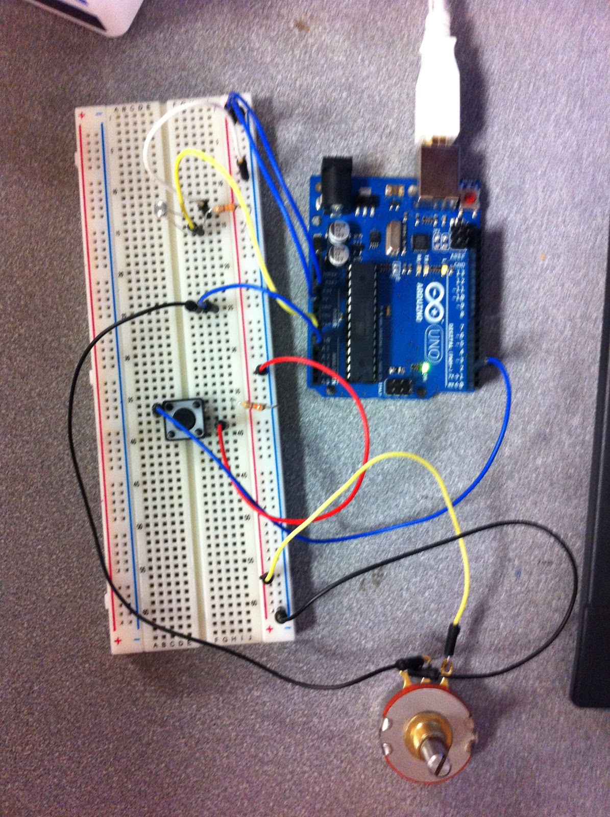
Building on the one way serial communication, this time we added a photo resistor and a potentiometer for our analog sensors along with the digital button sensor. Next, we read in the values from each sensor and sent the data to an output of values on the monitor in an orderly way so that we could determine which values came from which sensors.
The photo resistor (top left) and potentiometer (bottom right) connected to analog while the button sensor (middle left) is connected to digital.
With our sensor data coming in cleanly, we then wanted to use them for a greater purpose: moving a ball across the screen. To do this, we added some color and position variables and created the desired shape. Then the sensor values were connected to the variables, moving the ball backward, forward, up and down when the sensors were used. When the button is pressed, the ball appears. When the analog sensor's values change, it changes the ball's direction.
coding the arduino
processing to draw our output
Wireless Communication:
For wireless communication, we paired up with another group so that we could be the "input" group, or the door bell, and the other group was the "output" group, or the chime.
To begin, we made sure to use 3.3V of power because that is what the XBee takes. The XBee is a piece of hardware that allows us to create communication wirelessly. We connected the XBee to the breadboard along with a button switch. While the other group mounted their XBee with a output sensor that gives off a clicking noise.
The next step was to configure the XBees by using a USB Serial adapter board. We labeled the input group "0" and output group "1" and followed the steps to connect the radios wirelessly to one another with a personal id of "2345".
Once they were configured as a pair, we programmed the devices. The input code determined if the button was pressed and if so, to create output on the serial port. The output code looked for the output on the serial port and created a clicking noise if the output was found.
Finally, we added an LED to the input side in order to send two way communication back from the chime group to the button group. We then added code to the chime group that gave feedback to the button group saying they received the signal. The button code was then modified to read the feedback and flash the LED confirming the communication.
The "doorbell" circuit with an LED and button
the "chime" circuit
Problems:
When trying the wireless communication for the first time, we were running into an error that told us our device was not in sync. This was because we did not disconnect the wire from the digital pin 0 before uploading. This caused unwanted data to take the place of the output we wanted.
For our Final Project, we have decided to create a
physically interactive Risk game. Risk is a tactical multiplayer board game that
separates the world into territories and players strive to gain power over the
whole world by attacking other player’s territories.
To make it physically interactive, we will implement processing with hardware and create a projection onto a table or board that will be the "game board". This board will be "touch sensitive" and will detect players moves throughout the game including attacks, dice rolls and loosing territories. For people new to this game, there will also be a "help" button to aid users in understanding and to help the game to be played fairly.
Board games are an important part of learning and require players to be engaged to their position. The benefits of board games are impressive and Risk in particular: enhancing educational skills by teaching where things are located on a map, building self confidence when the hard work and strategy paid off, developing social and mental skills by communicating with other players and knowing their next move and encouraging problem solving and logic. The purpose of this project will be to engage more people into wanting to play this game by making it interactive allowing players to have more fun and feel in control.
Here are some examples of projectors with human interactivity:
This is how the actual board game looks. Our display will look similar to this:
For
this assignment, we created a screen drawing using a background image of a tree
as well as a simple leaf shape in a simple yellow color. We first had an
ellipse draw for the leaf but decided to make it more detailed with the leaf
shape which is a png image. We
used variables to parameterize the characteristics of our design such as the
background color, size, image, mouse position and direction. This way, the
choices can be changed at the top of the file instead of searching through the code
to find replacements. We
developed an algorithm for changing the direction the leaf is “floating”. If
the down arrow is pressed, the y position increases and the x position
increases making the leaf go towards the bottom right corner. If the other
arrows are pressed, the leaf increases and decreases the x and y positions in
the correct direction to change the leaf’s location across the page. When the
mouse is clicked, the leaf is given the x and y position of the mouse.
Problems:
While creating our animation, we had difficulty getting the leaf to our desired shape. One way to create a more leaf like image would be to use vertex() and connect multiple points together with noStroke().
Coca-Cola
Freestyle is an interactive touch screen soda fountain that has been added to
numerous restaurants since its debut in 2009. It offers the customer more drink
options (over 125) than the previous 6-8 option beverage dispenser and takes up
less room with its built in ice dispenser.
It is
used when people order a drink at fast-food restaurants. A customer gets their
drink from a cashier and walks to the device. They first push their cup against
the lever to dispense the ice. Then they sit the cup down and use the touch
screen to choose the “base” drink and additional flavors. When they are satisfied with the drink and flavor, they push the
"pour" button until the cup is full.
When observing
people using it, I noticed that some skip the ice part entirely. I also
noticed that during peak hours, a long line forms because the machine
can only serve one person at a time. Some people choose to just have the basic
drink choices such as water, coke, and sprite. Others want all the customization
of cherry-vanilla flavored Pibb Xtra or orange-vanilla Hi-C. Many times people had trouble with the soda overflowing the cup. I also saw
that people wanted to try new combinations and took a lot of time choosing
an option, tasting it, pouring it out, and starting over, bothering others
waiting behind.
The
whole transaction takes about 30 seconds if the user knows what they want and
about a minute if they are trying to decide. Getting the ice takes the least
amount of time. To speed up the process, there could be a sign above the
machine with all of the “base” drinks and then the additional flavors to choose
from. This way people waiting in line can decide what they want before it is
their turn, making the process faster.
For
Norman and Crawford, to interact well, both sides must listen, think, and speak
well with each other. Lacking in one of
these areas will result in low interaction. The Coca-cola Freestyle has a high
degree of interaction. The user tells the machine what it wants (touches the
drink they want), the machine “listens” to what the user told it, “thinks”
about the selection, and “speaks” by dispensing the drink. The user listens to
the machine, thinks about what the machine will do, and “speaks” by putting
their cup in the right place so the machine can give the soda.
The purpose of this lab was to use a transistor to control a high-current DC motor from the Arduino using a transistor and to control the direction using an H-bridge and a Relay.
Transistor:
When circuits include high-current loads like a DC motor that require more than the Arduino can supply, we need a transistor to control it. A transistor has 3 prongs: the "base" connects to the Arduino's output, the "collector" is attached to the element that has the high current, and the "emitter" connects to ground.
I started by connecting a potentiometer and transistor to the circuit. I then connected the motor to a power supply separate from the Arduino. I then connected a diode to protect my transistor from "back voltage" that occurs when the motor is turned off or changes direction. Finally, code was added to turn the motor on and off every second and then was changed to control speed with the potentiometer!
Direction:
To take the circuit a step further, we wanted to change its direction. To do this, we used an H-bridge which allows us to switch the polarity, changing the motor's direction. I added a switch to the circuit as well as a motor and H-bridge. The H-bridge can be confusing at first because of its many parts and because it looks so similar to the shift registers! I have included a diagram which made connecting it easier. Once the motor was connected to the h-bridge and to an external power source, I added code that turned the motor one way with current was high and the other direction when low.
Relays are devices that can also control large loads. I implemented a relay to also change the direction of the motor, but with a more satisfying "click" when the change is made! To begin, I made a circuit that alternated between turning on 2 LEDs. I then reassembled the wires by reversing the flow of current and attached the motor:
Problems:
When working with the relays, there was a problem with the prongs not reaching far enough to touch the metal in the breadboard. This was frustrating because although the wiring was correct, the desired outcome was not achieved until time was wasted trying to find the problem.
The purpose of this lab was to use see the usefulness of shift registers and how the work.
Shifting Out:
In previous labs, we have never used more than 8-10 pins at once. If we ever ran into a circuit that needed additional pins what would we do? Shift registers allow the Arduino to extend to many more pins than the ones on it's board. With one shift register you can control 8 outputs at once while only taking up a few pins on the microcontroller. If you need more pins, shift registers can connect to each other allowing more extensions.
Instead of using "asynchronous serial communication", the shift register works by "synchronous serial communication", pulsing a pin up and down which communicates a byte of data bit by bit while the clock pin delineated between them. When the byte is completely transmitted to the shift register, the high or low messages carried by each bit get allocated into the output of each LED. Shift registers can be confusing without the knowledge of each pin-out so I have included a drawing.
In the first circuit, just one shift register is used to light up 8 LEDs. Once connections were made to ground and power, the Serial Data Input, Shift Register Clock Pin, and Storage Register Clock Pin were connected. The LEDs were then added with resistors and connected to 8 pins around the register (Q0 - Q7). Finally the code was added to give a binary counting system to the LEDs:
In the second circuit, a second shift register was added without any additional wired to the Arduino. A "serial output" is used by an extra pin in one register to pass serial information from the Arduino out again without changing. This allows us to transmit 16 bits in a row using the second register. The first 8 bits flow through the first register to the second. The code was added to light all 16 LEDs one by one and other patterns:
Problems:
Although the shift registers clean up the wire collection on the Arduino, it asks for a lot of wires on the breadboards, as can be seen from the photos. With so many small, tight connections, it was difficult to make sure the connections were right the first try. Using the drawing of the shift register above made it easier to lay out where each where should connect to.
The kitchen is a unique part of every house and is a central gathering point for everyone. Whether eating a meal, doing chores, sharing stories or doing homework, the kitchen provides an inviting haven to stay. With such an inviting space comes a great door of opportunity for some ingenious inventions.
I was assigned the task of designing and prototyping a novel kitchen object with any or all of the elements I have used in previous labs.
Observation:
I began by observing my own kitchen at school as well as at home. I noticed while eating dinner with my family and asking for someone to "pass me the ____" that there was a place for improvement. While Lazy Susan's exist already, I thought it would be nice to improve the existing model. Currently, a Lazy Susan spins when the user pushes the circle in a clockwise or counter clockwise direction. But what if I could make that even easier? And make people believe that they have special powers?
The Design in my Head:
And so I began to design my Lazier Susan. It would still be a circular disk moving both directions but taking out the pushing aspect. The device would be controlled by hovering your hand over a sensor to make it go in the direction you pleased!
What's so Great About It?
Upon these thoughts I realized that this device could be used for more than just the kitchen table. If your kitchen comes with a large island, the Lazier Susan would serve as a nice piece to avoid walking to the other side. And why stop at the kitchen? This device would work very well in places like the robotics lab where many people are hovered around a counter and pieces are scattered everywhere. No more wasting time to walk to your needs, just have someone place it on the Lazier Susan and then hover over the desired direction pad and let it come to you!
The Dirty Work:
We started by getting just the breadboard and code to do what we wanted before adding the actual pieces. Using our previous knowledge of servo motors and photo resistors, we developed code to make the motor go one way when covering one photo resistor and vice versa.
Next, we took a piece of plywood and cut out a large circle. We then attached it to the servo using glue and screws and attached that to a wooden base for stability.
Because the diameter of the circle was so large, we wanted to give it more support for weight so we decided to construct platforms with wheels so when it spun the wheels would help it turn.
We then disconnected the photo resistors from the breadboard and placed them on the platform. We made them visually more appealing by creating foamcore platforms, one on either side, so users could understand how it works.
Demo:
Problems:
At first, our design included buttons and a musical tone that played as it spun. However, the delays on the song conflicted with the delays we wanted to give the circle so we decided to take it out and improve the interaction with users by making the buttons photo resistors instead.
The plywood we used unfortunately was not completely flat and therefore we ran into problems as it was spinning. Instead of a steady spin, the device did lots of wobbling. To fix this problem, we included the wheels to support the weight and lessen the wobbling.
In order to keep the circle still until the photo resistor is covered, we did a "calibration" that finds the average light from the resistor when first started and then when it is given less light than the average it tells it to spin.
The purpose of this lab was to familiarize myself with performing analog output with motor, servos, and piezo elements.
Pulse-Width Modulation:
Pulse-Width Modulation is a technique I used in order to get analog results (a range of results i.e. 0-255) with digital means (on or off). In order to make the digital output reflect an analog output, I can change the amount of time the light is in an off and on state. For example, If the light switches on for 1.5 milliseconds and off for .5 milliseconds then back to on repeatedly, the light would shine about 75% of its brightness. If the light is on for less and off for more of the time, the light will be more dim.
I connected a motor to the breadboard controlled by a potentiometer from the analog input side of the Arduino. When I turned the potentiometer one direction the motor would increase speed, and when I turned it the other way the speed would decrease. I also used Serial.print in my code in order to see the speed increase/decrease on the monitor.
A Single Servos:
While the motor from the last circuit helped demonstrate analog control, the motor is weak and can be stopped easily. Servos can also be used to control but because they include a small gearbox inside they give a more powerful movement and can also make it easier to control. The servo has 3 wires: signal, power, and ground.
I connected the Arduino to the white wire (signal) of the servo, the red wire (power) to the voltage, and the black wire (ground) to the ground. The code was a continuous loop making the servo "sweep" from side to side from 0 degrees to 180 degrees.
Music:
A piezo element allows for an output of sound. It works by creating a "click" for every pulse of current it is given. To make a song, I have to give it current at the right frequency. If you want the note A, the frequency will have to be 440 times a second. The frequency is so fast that the output of sound will run together and give you notes!
I connected my Arduino to my piezo element and gave it code that sends the correct frequencies to the piezo to create a the right tone.
Problems:
I ran into a problem while adding the potentiometer to my PWM circuit. The wiring was not correct so I checked myself by looking back at a previous lab to connect my circuit correctly. If you run into a problem with an addition to your circuit, try getting to addition to work by itself (in my case the potentiometer and an led) and then connect it to your current circuit the correct way.
The purpose of this lab was to practice preforming analog input with the Arduino.
Twisting:
For this circuit, I used a potentiometer connected the pins used for analog input which take a voltage (say 5 volts) and convert it to a digital number between 0 and 1023 (which is 5 volts). This is useful for a potentiometer because it allows a varying amount of resistance. I added an LED so that the varying resistance could be seen and then gave it code that make the LED blink at decreasing and increasing speeds depending on the twisting of the potentiometer.
Light:
I used photo resistors which sense the relative light for this light circuit which is useful for when I want it to be environmentally controlled. When the sensor is well lit a low value of light is produced, but when the sensor is in the dark it will produce a high value of light.
Temperature:
I used a temperature sensor made by another student which allowed me to measure temperature by an integrated circuit inside of the transistor. The Arduino takes in the values as digital values and then I used some math to convert it to degrees. I then used the debug window to output the value on the monitor!
Squeezing:
For this circuit I used a force sensitive resistor that is similar to a potentiometer used earlier except that its resistance varies with pressure instead of position. When there is no pressure the resistance is high and low when the pressure is high.
Problems:
When working with the temperature sensor, I continued to get incorrect readings. The problem was in my code. Make sure your conversions make sense mathematically or the values will be incorrect.
The purpose of this lab was to learn how to preform digital input and output with the Arduino and materials such as LEDs, motors, and buttons.
Blinking LED:
For my first circuit, I made a simple blinking LED by delaying it while it had power and then again when it did not have power.
I then improved upon the simple circuit by controlling the brightness of the LED like so:
8 LED Fun:
Next, I assembled a circuit that contained 8 LEDs and controlled then with code that included for loops (used to run a piece of code multiple times) and arrays (for managing a group of variables more easily) to keep the program small.
The first circuit turned all the LEDs on and then turned them all off. The code also included other fun animations such as turning on all LEDs one at a time and turning on all LEDs starting from the inside and working its way out giving an in and out effect.
This video shows the circuit doing all of the animations one after another:
Spin Motor Spin:
For this circuit, I used a transistor and a motor in my circuit which turned the motor on. I then played around with the code and made the motor accelerate and decelerate.
Button Pressing:
I added input to this circuit by included 2 small push buttons. I changed the circuit so that one button turns the LED on and the other turns it off. To make it better, I then made one button increase the brightness of the LED and the other button decrease the brightness.
State and Debouncing:
This circuit has a single push button. When you push and release the button the LED stays on until you push and release it again.
Reaction Challenge Game:
I designed and implemented a reaction challenge game that demonstrated my mastery of this lab. It involves both digital input and output. For this game, I set up a line of 7 LEDs with the one in the middle being red to indicate its importance. I also included a red LED and a green LED on the end for "win" and "lose". On the opposite end is a large push button for input.
The object of the game is for a player to push the button when the middle LED is lit. If the player does so, the green LED lights up and if not the red LED lights up.
There are 8 levels to the game and each level has an increased speed. The player has 3 lives and once they are used up the row of LEDs lights up the number of LEDs that matches the level the player got to.
I used many for loops and functions in this game for things like traversing through the LEDs, losing lives, and "winning" or "losing". To see the whole code that was used it can be seen here: The code
Problems:
During this lab, I encountered problems with weaker resistors or LEDs. It was important for the bulbs to be of equal brightness for aesthetic reasons so using trial and error I found LEDs that worked for me. Another way to do this would be to read the resistors and know the level you are working with.
The Psychopathology of Everyday Things is a chapter in the book The Design of Everyday Things by Donald A. Norman. This chapter addresses the frustration and psychology of everyday things as well as great techniques to provide well designed products. He gives numerous examples of everyday things that work along with big design failures. Here are some important ideas I drew from Norman's first chapter:
Questions that users have about a device should be answered easily by the
design, without the need for words or symbols or trial and error.
Designers should help the user by showing only the things that need to be
visible on a device. The lack of visibility makes a device difficult to operate
while an excess makes devices seem intimidating.
Affordances, the perceived and actual properties of something, give strong
clues as to how it works. Use this to your advantage instead of failing the
design with pictures, labels, or instructions.
If something happens right after an action, the user automatically believes
that it is a reaction to their action. If the behavior was not caused by the
action, it was poorly designed and allowed false causality.
If designers know how the mind works as well as how things work they can take
advantage of the things people are expected to know.
Good design makes things visible with good mappings, natural relationships
between controls and the controlled, and gives single controls single functions.
What the user intends for the control to do happens and it is rational, not
illogical, and consequential.
Bad design happens when the number of actions exceeds the number of controls
because the actions do not come naturally to the user. They will be required to
remember a pattern for the correct action.
A good designer takes time to consider the use of the device, the way that it
can be abused, the errors that can be made, and the functions people will
expect.
Technology is a paradox: The same technology that makes life easier by giving
us more control and options also complicates our life by making the devices so
complex that people cannot learn how to use it.
The paradox is no excuse. Using good design principles can make the
complexities manageable to the user.
These ideas will be very beneficial to me for the remainder of this course as well as afterward even though it was written in the 80's because the concepts of good design are still relevant today. As I continue in physical computing, I will use these ideas to create well designed devices that follow his guidelines and give the users an enjoyable experience.
In this lab, I learned how to construct a simple box made of foam core by first mastering the creation of corners (joint, lap, and larger radius) then developing a larger box.
Getting Started:
Before I began cutting the foam core, I familiarized myself with the tools and tips.
The X-Acto knife is the most important tool for this lab and keeping it sharp is imperative.
A metal straightedge is helpful for keeping sides straight and at 90 degree angles.
A large and cut proof surface keeps the knife from dulling and simplifies the work.
Adhesives like hot glue are important because they hold separate parts together (lap joints and folds)
Proper cutting techniques
use the whole blade instead of just the tip
don't cut through foam core all at once
Joining techniques include sharp, lap, and larger radius joints.
After understanding the basics, I began each corner the same way. I started out by using the metal straightedge and the X-Acto knife to give me straight sides and then to make the corners perfect 90 degree angles. Once complete. I was ready to start on the individual joints.
Cutting straight edges with the X-Acto knife and the straightedge.
Joint: Sharp
I cut through the straight-edged rectangle with the knife to the second sheet of paper (TO not THROUGH) and then bent the foam core back on itself to reiterate the cut. I then took the opposite end of the knife (being careful of the sharp edge) and forced a furrow along the line multiple times until the furrow is as deep as the thickness of the foam. Then I rotated the knife in the furrow to mold it into 45 degree angles.
Furrowing the foam core into a 45 degree angle.
Using the hot glue to hold the sides together, I folded the foam into a 90 degree angle and glued along the cut line. I allowed the glue to dry before letting the foam core sit on its own.
Holding the foam core at a 90 degree angle until the glue was dry.
The completed sharp joint.
Joint: Lap
Starting again with the straight-edged rectangle, this time I cut the foam core all the way through to give my two separate pieces. I laid one piece flat on the table and placed the other perpendicularly and flush on top of it. With my knife, I made soft slits where the vertical edge met the horizontal surface. This gave me a line of equal thickness as the width of the foam core. I then followed the lines with a deeper cut to the opposite side but not through it. I "flicked" off the edge of the cut side with a flat head screwdriver being careful not to break the back paper (just taking off the top layer and the foam inside). I ran the hot glue gun on the edge with no foam and then pressed my second piece directly on to the flap perpendicularly from the first piece creating a 90 degree angle.
The first piece after cutting the edge to equal the width and flicking off the top and middle layer.
Completed lap joint.
Completed lap joint (you can see how the two separate pieces are joined perpendicularly to one another)
Joint: Larger Radius
This joint is a little more intricate than the others. Starting with the same straight-edged rectangle, I worked from the center of the piece and cut out 1/8" strips of foam, going about halfway through and removing the top layer of paper CAREFULLY leaving the foam attached. Then I bent the foam closed going past the intended angle. If you are not satisfied with your angle, you can cut out more slits in the foam until you get a good angle. I then hot glued over the notches and set my desired angle.
Cutting the small slits in the foam board.
Completed larger radius joint.
Simple Box:
With all the joint practice, it was then time to put my knowledge to work and create a box starting out with two squares and one longer rectangle of foam core. Starting out at one end of the rectangle I measured three inches from the edge, and using my straightedge I cut a deep slit. I used the techniques from the sharp joint and made the first joint. I then measured five inches from the new edge and created another sharp joint. I continued the three inches and five inches once more until I had a cube shape with some excess overlap. I cut the excess off with a knife and made a lap joint to hold the two unattached edges together. I then measured the openings of the box on both sides and cut the measurements out on the two square pieces. I then made lap joints from these pieces and hot glued one to its appropriate side. With the last opening I also did a lap joint; however, I did not glue the pieces together! Instead I just made very exact measurements so that the pieces fit together tightly, but were still able to be taken apart when needed. This is important so that I can use the box to hold the breadboard or whatever else needs to be inside.
Creating the sharp joints for the three corners.
First joint completed.
Second joint completed.
Four joints completed!
After assembling the two sides!
All in a day's work in the lab!
Problems:
When working on the larger radius joint, I found it difficult to only remove the top paper layer and accidentally removed some foam. This was difficult because the paper was pre-laminated and therefore very attached to the foam. Use patience when removing this section because you do not want gaps in your joint.
Helpful Links:
For more information about foam core construction: