Overview:
The purpose of this lab was to (1) send data to the computer using a sensor and have the computer graph the output visually, (2) send data from multiple sensors, and (3) create a wireless communication.
1 Way Serial Communication:
I began by connecting a potentiometer to an analog pin in the Arduino. I then programmed the Arduino to read the potentiometer and display the results on the Serial monitor using Serial.write():

Using Serial.write() made it challenging to understand the output because it was not sending the data as an ASCII character. To make it readable, I used an application called CoolTerm that shows the incoming bytes as ASCII or hexadecimal characters. The data then looked like this instead:

Next, I wanted to graph the values I was receiving from the potentiomenter with Processing. I set up my code with the correct library, window size, port and colors then created a method that read the input and printed it. Finally, I drew the graph with the input... and Viola!

I thought the potentiometer seemed rather boring so I switched sensors to this photoresistor for another neat effect!

2 Way Serial Communication:
Building on the one way serial communication, this time we added a photo resistor and a potentiometer for our analog sensors along with the digital button sensor. Next, we read in the values from each sensor and sent the data to an output of values on the monitor in an orderly way so that we could determine which values came from which sensors.
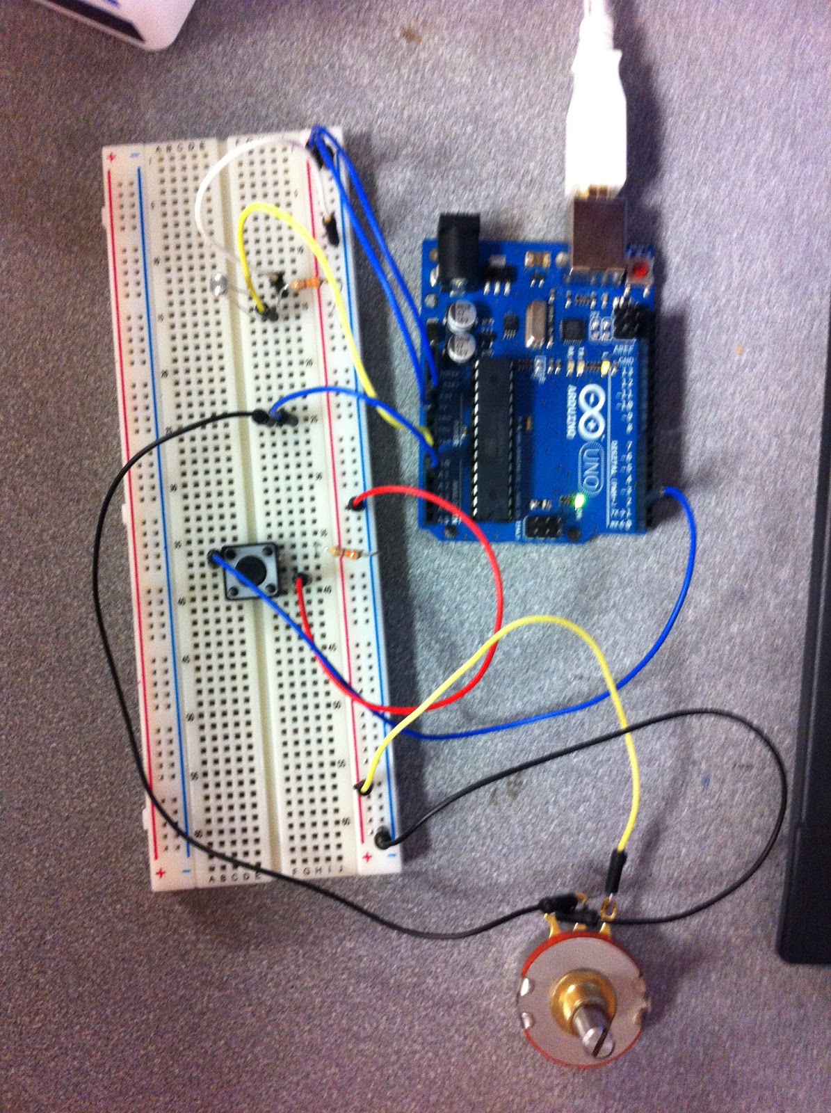 |
| The photo resistor (top left) and potentiometer (bottom right) connected to analog while the button sensor (middle left) is connected to digital. |
With our sensor data coming in cleanly, we then wanted to use them for a greater purpose: moving a ball across the screen. To do this, we added some color and position variables and created the desired shape. Then the sensor values were connected to the variables, moving the ball backward, forward, up and down when the sensors were used. When the button is pressed, the ball appears. When the analog sensor's values change, it changes the ball's direction.
 |
| coding the arduino |
 |
| processing to draw our output |
Wireless Communication:
For wireless communication, we paired up with another group so that we could be the "input" group, or the door bell, and the other group was the "output" group, or the chime.
To begin, we made sure to use 3.3V of power because that is what the XBee takes. The XBee is a piece of hardware that allows us to create communication wirelessly. We connected the XBee to the breadboard along with a button switch. While the other group mounted their XBee with a output sensor that gives off a clicking noise.
The next step was to configure the XBees by using a USB Serial adapter board. We labeled the input group "0" and output group "1" and followed the steps to connect the radios wirelessly to one another with a personal id of "2345".
Once they were configured as a pair, we programmed the devices. The input code determined if the button was pressed and if so, to create output on the serial port. The output code looked for the output on the serial port and created a clicking noise if the output was found.


Finally, we added an LED to the input side in order to send two way communication back from the chime group to the button group. We then added code to the chime group that gave feedback to the button group saying they received the signal. The button code was then modified to read the feedback and flash the LED confirming the communication.
 |
| The "doorbell" circuit with an LED and button |
 |
| the "chime" circuit |
Problems:
When trying the wireless communication for the first time, we were running into an error that told us our device was not in sync. This was because we did not disconnect the wire from the digital pin 0 before uploading. This caused unwanted data to take the place of the output we wanted.