Monday, September 24, 2012

Lab: Analog Input

Overview:

The purpose of this lab was to practice preforming analog input with the Arduino.

Twisting:

For this circuit, I used a potentiometer connected the pins used for analog input which take a voltage (say 5 volts) and convert it to a digital number between 0 and 1023 (which is 5 volts). This is useful for a potentiometer because it allows a varying amount of resistance. I added an LED so that the varying resistance could be seen and then gave it code that make the LED blink at decreasing and increasing speeds depending on the twisting of the potentiometer.

Light:

I used photo resistors which sense the relative light for this light circuit which is useful for when I want it to be environmentally controlled. When the sensor is well lit a low value of light is produced, but when the sensor is in the dark it will produce a high value of light.

Temperature:

I used a temperature sensor made by another student which allowed me to measure temperature by an integrated circuit inside of the transistor. The Arduino takes in the values as digital values and then I used some math to convert it to degrees. I then used the debug window to output the value on the monitor!

Squeezing:

For this circuit I used a force sensitive resistor that is similar to a potentiometer used earlier except that its resistance varies with pressure instead of position. When there is no pressure the resistance is high and low when the pressure is high.

Problems:

When working with the temperature sensor, I continued to get incorrect readings. The problem was in my code. Make sure your conversions make sense mathematically or the values will be incorrect.

For more Information:

Monday, September 17, 2012

Lab: Digital Input/Output

Overview:

The purpose of this lab was to learn how to preform digital input and output with the Arduino and materials such as LEDs, motors, and buttons. 

Blinking LED:

For my first circuit, I made a simple blinking LED by delaying it while it had power and then again when it did not have power. 

I then improved upon the simple circuit by controlling the brightness of the LED like so:

8 LED Fun:

Next, I assembled a circuit that contained 8 LEDs and controlled then with code that included for loops (used to run a piece of code multiple times) and arrays (for managing a group of variables more easily) to keep the program small.

The first circuit turned all the LEDs on and then turned them all off. The code also included other fun animations such as turning on all LEDs one at a time and turning on all LEDs starting from the inside and working its way out giving an in and out effect.

This video shows the circuit doing all of the animations one after another:

Spin Motor Spin:

For this circuit, I used a transistor and a motor in my circuit which turned the motor on. I then played around with the code and made the motor accelerate and decelerate.

Button Pressing:

I added input to this circuit by included 2 small push buttons. I changed the circuit so that one button turns the LED on and the other turns it off. To make it better, I then made one button increase the brightness of the LED and the other button decrease the brightness.

State and Debouncing:

This circuit has a single push button. When you push and release the button the LED stays on until you push and release it again.

Reaction Challenge Game:

I designed and implemented a reaction challenge game that demonstrated my mastery of this lab. It involves both digital input and output. For this game, I set up a line of 7 LEDs with the one in the middle being red to indicate its importance. I also included a red LED and a green LED on the end for "win" and "lose". On the opposite end is a large push button for input.

The object of the game is for a player to push the button when the middle LED is lit. If the player does so, the green LED lights up and if not the red LED lights up. 

There are 8 levels to the game and each level has an increased speed. The player has 3 lives and once they are used up the row of LEDs lights up the number of LEDs that matches the level the player got to.


I used many for loops and functions in this game for things like traversing through the LEDs, losing lives, and "winning" or "losing". To see the whole code that was used it can be seen here: The code

Problems:

During this lab, I encountered problems with weaker resistors or LEDs. It was important for the bulbs to be of equal brightness for aesthetic reasons so using trial and error I found LEDs that worked for me. Another way to do this would be to read the resistors and know the level you are working with.

Links:

For more information on digital input and output:

Sunday, September 16, 2012

The Design of Everyday Things


The Psychopathology of Everyday Things is a chapter in the book The Design of Everyday Things by Donald A. Norman. This chapter addresses the frustration and psychology of everyday things as well as great techniques to provide well designed products. He gives numerous examples of everyday things that work along with big design failures. Here are some important ideas I drew from Norman's first chapter:

  • Questions that users have about a device should be answered easily by the design, without the need for words or symbols or trial and error.
  • Designers should help the user by showing only the things that need to be visible on a device. The lack of visibility makes a device difficult to operate while an excess makes devices seem intimidating.
  • Affordances, the perceived and actual properties of something, give strong clues as to how it works. Use this to your advantage instead of failing the design with pictures, labels, or instructions.
  • If something happens right after an action, the user automatically believes that it is a reaction to their action. If the behavior was not caused by the action, it was poorly designed and allowed false causality.
  • If designers know how the mind works as well as how things work they can take advantage of the things people are expected to know.
  • Good design makes things visible with good mappings, natural relationships between controls and the controlled, and gives single controls single functions. What the user intends for the control to do happens and it is rational, not illogical, and consequential.
  • Bad design happens when the number of actions exceeds the number of controls because the actions do not come naturally to the user. They will be required to remember a pattern for the correct action.
  • A good designer takes time to consider the use of the device, the way that it can be abused, the errors that can be made, and the functions people will expect.
  • Technology is a paradox: The same technology that makes life easier by giving us more control and options also complicates our life by making the devices so complex that people cannot learn how to use it.
  • The paradox is no excuse. Using good design principles can make the complexities manageable to the user. 
These ideas will be very beneficial to me for the remainder of this course as well as afterward even though it was written in the 80's because the concepts of good design are still relevant today. As I continue in physical computing, I will use these ideas to create well designed devices that follow his guidelines and give the users an enjoyable experience. 

Monday, September 10, 2012

Lab: Foam Core Construction

Overview: 

In this lab, I learned how to construct a simple box made of foam core by first mastering the creation of corners (joint, lap, and larger radius) then developing a larger box.

Getting Started:

Before I began cutting the foam core, I familiarized myself with the tools and tips. 
  • The X-Acto knife is the most important tool for this lab and keeping it sharp is imperative.
  • A metal straightedge is helpful for keeping sides straight and at 90 degree angles. 
  • A large and cut proof surface keeps the knife from dulling and simplifies the work.
  • Adhesives like hot glue are important because they hold separate parts together (lap joints and folds)
  • Proper cutting techniques
    • use the whole blade instead of just the tip
    • don't cut through foam core all at once
  • Joining techniques include sharp, lap, and larger radius joints.
After understanding the basics, I began each corner the same way. I started out by using the metal straightedge and the X-Acto knife to give me straight sides and then to make the corners perfect 90 degree angles. Once complete. I was ready to start on the individual joints.
Cutting straight edges with the X-Acto knife and the straightedge.

Joint: Sharp

I cut through the straight-edged rectangle with the knife to the second sheet of paper (TO not THROUGH) and then bent the foam core back on itself to reiterate the cut. I then took the opposite end of the knife (being careful of the sharp edge) and forced a furrow along the line multiple times until the furrow is as deep as the thickness of the foam. Then I rotated the knife in the furrow to mold it into 45 degree angles.
Furrowing the foam core into a 45 degree angle. 
Using the hot glue to hold the sides together, I folded the foam into a 90 degree angle and glued along the cut line. I allowed the glue to dry before letting the foam core sit on its own. 
Holding the foam core at a 90 degree angle until the glue was dry.
The completed sharp joint.

Joint: Lap

Starting again with the straight-edged rectangle, this time I cut the foam core all the way through to give my two separate pieces. I laid one piece flat on the table and placed the other perpendicularly and flush on top of it. With my knife, I made soft slits where the vertical edge met the horizontal surface. This gave me a line of equal thickness as the width of the foam core. I then followed the lines with a deeper cut to the opposite side but not through it. I "flicked" off the edge of the cut side with a flat head screwdriver being careful not to break the back paper (just taking off the top layer and the foam inside). I ran the hot glue gun on the edge with no foam and then pressed my second piece directly on to the flap perpendicularly from the first piece creating a 90 degree angle. 
The first piece after cutting the edge to equal the width and flicking off the top and middle layer.
Completed lap joint.
Completed lap joint (you can see how the two separate pieces are joined perpendicularly to one another)

Joint: Larger Radius

This joint is a little more intricate than the others. Starting with the same straight-edged rectangle, I worked from the center of the piece and cut out 1/8" strips of foam, going about halfway through and removing the top layer of paper CAREFULLY leaving the foam attached. Then I bent the foam closed going past the intended angle. If you are not satisfied with your angle, you can cut out more slits in the foam until you get a good angle. I then hot glued over the notches and set my desired angle. 
Cutting the small slits in the foam board. 
Completed larger radius joint. 

Simple Box:

With all the joint practice, it was then time to put my knowledge to work and create a box starting out with two squares and one longer rectangle of foam core. Starting out at one end of the rectangle I measured three inches from the edge, and using my straightedge I cut a deep slit. I used the techniques from the sharp joint and made the first joint. I then measured five inches from the new edge and created another sharp joint. I continued the three inches and five inches once more until I had a cube shape with some excess overlap. I cut the excess off with a knife and made a lap joint to hold the two unattached edges together. I then measured the openings of the box on both sides and cut the measurements out on the two square pieces. I then made lap joints from these pieces and hot glued one to its appropriate side. With the last opening I also did a lap joint; however, I did not glue the pieces together! Instead I just made very exact measurements so that the pieces fit together tightly, but were still able to be taken apart when needed. This is important so that I can use the box to hold the breadboard or whatever else needs to be inside. 
Creating the sharp joints for the three corners.
First joint completed.
Second joint completed. 
Four joints completed!
After assembling the two sides!
All in a day's work in the lab!

Problems:

When working on the larger radius joint, I found it difficult to only remove the top paper layer and accidentally removed some foam. This was difficult because the paper was pre-laminated and therefore very attached to the foam. Use patience when removing this section because you do not want gaps in your joint. 

Helpful Links:

For more information about foam core construction:

Sunday, September 9, 2012

Imaginary Expressive Object


I came up with an imaginary expressive object called a Toilet Paper/Paper Towel Wall Storage. Having this device is convenient for everyone because it gives a nice storage place for the paper saving counter and cabinet space, and it makes sure you know when you need more; before it's too late!

This device specifically is for anything cylinder shaped that needs storage, but specifically toilet paper for the bathroom and paper towels in the kitchen. You can open the device from the wall and fill the bin up with your rolls. As a roll becomes empty, all you have to do is take the empty roll off and the device will take a new roll from the storage and bring it to the front. When there is one roll left inside the wall, the device will show a yellow light letting you know that you need to restock. When it is completely empty, the light shines red. When there is plenty in storage, the green light stays on.

The device could either be made to feel when the roll is empty and refill itself, or it there could be a way for you to push a button and it would then get a new roll. The device would be pretty simple and self explanatory because people can easily associate green with good (or full), yellow with warning (getting low), and red with danger (empty).

This device could be necessary because will uncluttered the home (or at least help!). It also serves as a helpful reminder for when you need to go to the store for more.

Saturday, September 8, 2012

Lab: Parts Kit, Breadboard, Basic Electronics, and Switches


Overview:

The purpose of this lab was to become familiar with the different parts we will be working with as the semester continues and to construct a few circuits on our own with the many parts. 

Parts Kit:

We were equipped with the following materials for the lab:


  • Plastic container (in which everything else is)
  • Arduino Uno (microcontroller)
  • 3ft USB cable
  • 1 big pushbutton
  • 2 small pushbuttons
  • 3 assorted LEDs
  • 2 mini-LEDs (red/green)
  • 1 tri-color LED
  • 1 flex sensor
  • 1 softpot (pressure-sensitive resistor)
  • 1 potentiometer
  • 2 P2N2222 transistors
  • 1 7805 voltage regulator
  • 3 resistors each of:
    • 150 Ω
    • 330 Ω
    • 10K Ω (10,000 Ω)
  • breadboard
  • 3 alligator test clips


Electronics: 

Once I familiarized myself with the different components and measured continuity (whether or not there is a connection between 2 points) using the multimeter, I started setting up my breadboard. I first chose to use the 9v DC power supply to give my circuit power.

Basic LED Circuit:

I started with a basic LED circuit. I first disconnected my power supply then added a switch, a resistor, and a LED in a series (remember that the long leg goes to the voltage and the short leg goes to ground) like so:
This is a drawing of what the circuit will look like. The square is our power supply. The line with a break in it is the switch. The zig zag is where the resistor is. The triangle with arrows coming from it is the LED.
This picture shows a better idea of what the circuit will look like on the breadboard.

An aerial view of the actual circuit.
A profile view of the circuit with the LED.
When the button is pressed, the LED light shines because the switch is allowing the current to go through. The resistor plays an important role because it makes sure that the LED does not get more power than it needs. When you lift your finger off the button, the switch opens and the light turns back off as you can see in this video:


Components in Series:

The next circuit I built was similar to the first but I added an additional LED in a series like this:
A drawing of the series circuit. The square is the power supply, the broken line is the switch, the zig zag is the resistor, and the 2 triangles with arrows represent the 2 LEDs.
This is a picture of what the circuit will look like on the breadboard.
This is an aerial view of the 2 LED's in series.

If you were to measure the voltage across the resistor and each LED, the voltage would not match up with the total voltage from the power to ground because some of the energy is emitted as heat!

Components in Parallel:

I then created a parallel circuit with 3 LEDs
Here is is easy to see the the 3 LEDs are in parallel and sharing the same amount of voltage between them.


Generating a Variable Voltage with a Potentiometer:

In this circuit, I used a potentiometer (a resistor with the ability to change resistance) to create a dimming effect the LEDs.

A potentiometer works like this:
-There are 3 extensions from the device that are connections. The 2 outer ones are connected to a resistor with a fixed value.  The center connection is connected to a slider that slides across the fixed resistor which changes the resistance between the center connection to either outside connection. This change in resistance dims and brightens the light!


This picture shows the potentiometer with the 3 connections
This is the potentiometer in action!
I then took out the battery power supply and tried the same circuit using an Arduino connected to a USB as my power supply. The results were the same as expected:

Problems:

The first time I tested the parallel circuit with the 3 LEDs, only 2 LED lit up. I was using 2 regular LEDs and 1 tri-color LED. The tri-color LED was not lighting up because it needed more power than the circuit could give it. When we switched the tri-color LED out with a mini LED, all 3 lights worked. For future reference, make sure you have enough power for the loads you are working with!

For more information:
Monday, September 3, 2012

Sensor Walk

When taking the time to seek out sensors, one can become overwhelmed with the number of sensors they encounter in a day. These are a few of the countless sensors I found around my apartment at Berry.


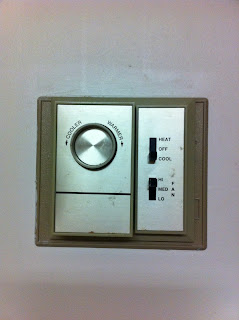
This is our thermostat that tracks our apartment's heating and cooling. The sensor detects when the air is not at the desired temperature and heats/cools until it is reached.


This is a Brita water pitcher. It has an electronic sensor that tells us when the filter needs replacing.


This is my laptop touch pad. The sensor it uses is called a tactile sensor which means it is sensitive to touch, force or pressure which is useful for navigation because it translates the motion and position of touch into a relative position on the screen. 


This sensor detects student's key cards and unlocks the door giving access to the hall. It does not work with just any Berry card and some cards work at different times. 


This speaker is another example of tactile sensors.  To turn the volume up and down, you tap lightly on the "+" and "-" buttons on either side. To turn the speaker off, you tap both sides simultaneously. 


This is a fire alarm. When it senses a fire, it makes a loud noise and flashes lights.


This is a Keurig coffee maker. There are lots of sensors attached to it. One in particular detects when the water is below a certain level and flashes a light indicating the need for more water.

Saturday, September 1, 2012

Lab: Soldering

Overview:

The purpose of this lab was to learn how to solder. This is a useful skill to have if ever doing electronics work. The lab showed me how to solder DC Power jacks and plugs to connectors and battery holders for wiring up a breadboard, a task I had never done before.

Preparation and Soldering:

After Dr. Hamid briefed me on the safety concerns of soldering, I entered the Robotics Lab to begin. First, I cut 4 inches of red and black 22-AWG hookup wire. Once I stripped the plastic ends off using a wire stripper, I attempted to solder them*. As a beginner, it took a few extra minutes to get comfortable with the soldering iron and get it to correctly solder the copper wire. I then unscrewed the power jack and hooked one red end around the inside tab of the jack and one black end around the further tab. I placed the soldering iron on the ends to seal them against the metal tabs, being careful to not let the separate wires touch. I returned the covering of the power jack over the tabs. To the other end of the red and black wire I soldered on a pair of header pins (one to the black wire and one to the white). To ensure that the wires did not cross, I applied heat shrink tubing around where the wires and header pins met. 

Then, I took a battery snap that had red and black wire already connected to it. I twisted the wires and soldered the opposite ends. I then unscrewed the power plug (making sure to keep it on the wires, but just moved down out of the way for now) and repeated the process of soldering the red wire to the inside tab and the black wire to the further tab. Once soldered, I screwed the plug cover back over the tabs. 

The completed connection with labeled materials and equipment.


Testing:

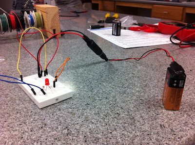
I was then ready to test the connections! I fastened the 9v battery to our battery snap and then inserted the power plug into the power jack. I connected the end with the header pins to a breadboard set up with a test circuit and LED and watched as the LED emitted light, affirming my satisfactory soldering work!


Problems:

Although I did get a successful result, there were a few road bumps I hit that future solderers can avoid. 

First, it took my soldering iron a LONG time to solder my first wire. I learned that occasionally, the iron tip needs a method called 'tinning', melting a little solder on the tip of the iron at the beginning of using it, which his helps the heat flow from the iron's tip to the joint. Once I corrected the problem, the copper wire was getting hot enough to soak in the solder. 

The other issue I ran into was taking the power jack's cover completely off of the wire and forgetting to put it back on before sealing both ends. In this case, I had to take extra time out of the project to desolder one end and slide the cover back over the jack. 

* Pre-soldering the wires was a tip I was given from a more experienced solderer. Applying the solder to the wire while attaching to the parts is also a great way!

More Help:

For more information on this topic here are some really helpful resources: