Overview:
The purpose of this lab was to become familiar with the different parts we will be working with as the semester continues and to construct a few circuits on our own with the many parts.
Parts Kit:
We were equipped with the following materials for the lab:
- Plastic container (in which everything else is)
- Arduino Uno (microcontroller)

- 1 big pushbutton
- 1 softpot (pressure-sensitive resistor)
Electronics:
When the button is pressed, the LED light shines because the switch is allowing the current to go through. The resistor plays an important role because it makes sure that the LED does not get more power than it needs. When you lift your finger off the button, the switch opens and the light turns back off as you can see in this video:
Components in Series:
The next circuit I built was similar to the first but I added an additional LED in a series like this:
 |
| A drawing of the series circuit. The square is the power supply, the broken line is the switch, the zig zag is the resistor, and the 2 triangles with arrows represent the 2 LEDs. |
 |
| This is a picture of what the circuit will look like on the breadboard. |
 |
| This is an aerial view of the 2 LED's in series. |
If you were to measure the voltage across the resistor and each LED, the voltage would not match up with the total voltage from the power to ground because some of the energy is emitted as heat!
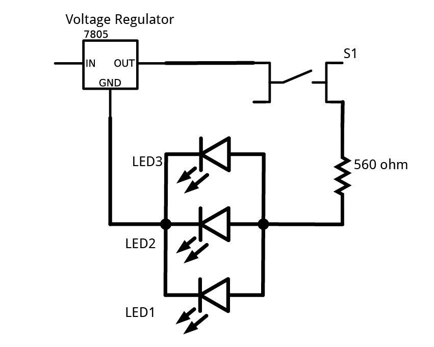
Components in Parallel:
I then created a parallel circuit with 3 LEDs
 |
| Here is is easy to see the the 3 LEDs are in parallel and sharing the same amount of voltage between them. |
Generating a Variable Voltage with a Potentiometer:
In this circuit, I used a potentiometer (a resistor with the ability to change resistance) to create a dimming effect the LEDs.
A potentiometer works like this:
-There are 3 extensions from the device that are connections. The 2 outer ones are connected to a resistor with a fixed value. The center connection is connected to a slider that slides across the fixed resistor which changes the resistance between the center connection to either outside connection. This change in resistance dims and brightens the light!
 |
| This picture shows the potentiometer with the 3 connections |
This is the potentiometer in action!
I then took out the battery power supply and tried the same circuit using an Arduino connected to a USB as my power supply. The results were the same as expected:
Problems:
The first time I tested the parallel circuit with the 3 LEDs, only 2 LED lit up. I was using 2 regular LEDs and 1 tri-color LED. The tri-color LED was not lighting up because it needed more power than the circuit could give it. When we switched the tri-color LED out with a mini LED, all 3 lights worked. For future reference, make sure you have enough power for the loads you are working with!
For more information:


No comments:
Post a Comment